


 Hướng dẫn kỹ thuật
 CÔNG TY CỔ PHẦN DỊCH VỤ CÔNG NGHỆ DATECH

Số 23E4 KĐT Cầu Diễn, Tổ 7, Phú Diễn, Bắc Từ Liêm, Hà Nội

Email: sales@datech.vn
 Danh mục sản phẩm
CÔNG TY CỔ PHẦN DỊCH VỤ CÔNG NGHỆ DATECH
Số 23E4 KĐT Cầu Diễn, Tổ 7, Phú Diễn, Bắc Từ Liêm, Hà Nội
Danh mục sản phẩm
 Bộ lưu điện UPS

13/12/2021

13/12/2021
Danh sách nội dung [Ẩn]
Hướng dẫn cấu hình Inter-AS VPLS với xử lý MAC tại ASBR trên các thiết bị MX Series (router)
Ví dụ này mô tả cách cấu hình dịch vụ LAN riêng ảo (VPLS – Virtual Private LAN Service) giữa các hệ thống tự trị (Inter-AS), với chức năng xử lý địa chỉ MAC tại ASBR, giữa VPLS sử dụng tín hiệu BGP và VPLS sử dụng tín hiệu LDP. Tính năng này được mô tả trong RFC 4761 với tên gọi là multi-AS VPLS option E hoặc method E.
Ví dụ này được tổ chức theo các phần sau:
Để hỗ trợ Inter-AS VPLS giữa BGP-signaled VPLS và LDP-signaled VPLS, mạng của bạn phải đáp ứng các yêu cầu phần cứng và phần mềm sau:
VPLS là công nghệ quan trọng cho việc cung cấp dịch vụ Ethernet dạng multipoint. Các nhà cung cấp dịch vụ lớn đã triển khai mạng lõi dựa trên IP và MPLS để cung cấp dịch vụ VPLS cho các doanh nghiệp lớn. Nhu cầu ngày càng tăng khiến hệ thống VPLS cần mở rộng quy mô để hỗ trợ nhiều khách hàng VPLS có các site phân tán trên nhiều khu vực địa lý. BGP-signaled VPLS mang lại lợi thế về khả năng mở rộng so với LDP-signaled VPLS. Trong một số môi trường, cần thiết phải có khả năng tương tác giữa VPLS sử dụng BGP và VPLS sử dụng LDP.
Ví dụ này trình bày một cách cấu hình để kết nối VPLS sử dụng tín hiệu BGP với mạng VPLS hiện tại sử dụng tín hiệu LDP.
Lợi ích của cấu hình này:
Lưu lượng từ các dịch vụ VPLS liên kết sẽ được chuyển mạch tại ASBR. ASBR thực hiện toàn bộ hoạt động mặt phẳng dữ liệu (data plane): flooding, học địa chỉ MAC, aging, và chuyển tiếp MAC cho mỗi AS, để định tuyến lưu lượng giữa các giao diện kết nối với khách hàng và giữa các pseudowire được thiết lập đầy đủ trong AS. Một pseudowire duy nhất được tạo giữa các ASBR trên liên kết inter-AS, và các ASBR này sẽ chuyển tiếp lưu lượng từ pseudowire trong mỗi AS sang ASBR phía đối diện.
Mỗi ASBR thực hiện các hoạt động VPLS trong phạm vi AS nội bộ của mình, và cũng thực hiện VPLS với ASBR ở AS bên kia. ASBR coi AS bên kia là một site trong BGP-signaled VPLS. Để thiết lập pseudowire VPLS, các thông điệp VPLS NLRI sẽ được trao đổi thông qua các phiên EBGP trên các liên kết inter-AS giữa các ASBR.
Trong ví dụ này mạng metro được cấu hình với VPLS sử dụng LDP. Mạng lõi (core) được cấu hình với VPLS sử dụng BGP.
Phần đầu tiên của ví dụ trình bày các bước cơ bản để cấu hình các interface logic, OSPF, iBGP, LDP và MPLS. Phần này giống với các cấu hình thông thường cho VPLS sử dụng LDP hoặc BGP.
Phần độc đáo của ví dụ nằm ở cấu hình routing instance cho VPLS, EBGP, và chính sách (policy) dùng để đưa các route học được từ các route trực tiếp và từ OSPF vào bảng định tuyến BGP. Thông tin chi tiết về các câu lệnh cấu hình sẽ được mô tả trong phần hướng dẫn từng bước.
Sơ đồ mạng
Hình 1: Topology ví dụ Inter-AS VPLS với xử lý MAC tại ASBR 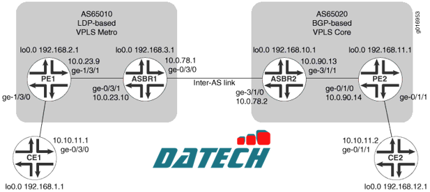
Để cấu hình Inter-AS VPLS giữa BGP-signaled VPLS và LDP-signaled VPLS, hãy thực hiện các bước sau.
**Lưu ý: Trong bất kỳ phiên cấu hình nào, bạn nên định kỳ sử dụng lệnh commit check để kiểm tra xem cấu hình có thể được commit mà không có lỗi hay không.
Cấu hình các giao diện (Interfaces)
Thủ tục từng bước
Để cấu hình các giao diện:
user@CE1# set interfaces lo0 unit 0 family inet address 192.168.1.1/32 primary user@PE1# set interfaces lo0 unit 0 family inet address 192.168.2.1/32 primary user@ASBR1# set interfaces lo0 unit 0 family inet address 192.168.3.1/32 primary user@ASBR2# set interfaces lo0 unit 0 family inet address 192.168.10.1/32 primary user@PE2# set interfaces lo0 unit 0 family inet address 192.168.11.1/32 primary user@CE2# set interfaces lo0 unit 0 family inet address 192.168.12.1/32 primary |
user@host> commit check |
configuration check succeeds |
user@host> commit |
commit complete |
user@host> show interfaces lo0 Physical interface: lo0, Enabled, Physical link is Up Interface index: 6, SNMP ifIndex: 6 Type: Loopback, MTU: Unlimited Device flags : Present Running Loopback Interface flags: SNMP-Traps Link flags : None Last flapped : Never Input packets : 0 Output packets: 0 Logical interface lo0.0 (Index 75) (SNMP ifIndex 16) Flags: SNMP-Traps Encapsulation: Unspecified Input packets : 0 Output packets: 0 Protocol inet, MTU: Unlimited Flags: None Addresses Local: 127.0.0.1 Addresses, Flags: Primary Is-Default Is-Primary Local: 192.168.3.1 Logical interface lo0.16384 (Index 64) (SNMP ifIndex 21) Flags: SNMP-Traps Encapsulation: Unspecified Input packets : 0 Output packets: 0 Protocol inet, MTU: Unlimited Flags: None Addresses Local: 127.0.0.1 Logical interface lo0.16385 (Index 65) (SNMP ifIndex 22) Flags: SNMP-Traps Encapsulation: Unspecified Input packets : 0 Output packets: 0 Protocol inet, MTU: Unlimited Flags: None |
Trong ví dụ trên, lưu ý rằng địa chỉ local chính của giao diện lo0 cho protocol family inet trên Router ASBR1 là 192:168:3:1.
user@CE1# set interfaces ge-0/3/0 unit 0 family inet address 10.10.11.1/24 user@PE1# set interfaces ge-1/3/1 unit 0 family inet address 10.0.23.9/30 user@ASBR1# set interfaces ge-0/3/1 unit 0 family inet address 10.0.23.10/30 user@ASBR1# set interfaces ge-0/3/0 unit 0 family inet address 10.0.78.1/30 user@ASBR2# set interfaces ge-3/1/0 unit 0 family inet address 10.0.78.2/30 user@ASBR2# set interfaces ge-3/1/1 unit 0 family inet address 10.0.90.13/30 user@PE2# set interfaces ge-0/1/0 unit 0 family inet address 10.0.90.14/30 user@CE2# set interfaces ge-0/1/1 unit 0 family inet address 10.10.11.2/24 |
user@host> commit check |
configuration check succeeds |
user@host> commit |
commit complete |
user@ASBR2> show interfaces ge-* terse Interface Admin Link Proto Local Remote ge-3/1/0 up up ge-3/1/0.0 up up inet 10.0.78.2/30 multiservice ge-3/1/1 up up ge-3/1/1.0 up up inet 10.0.90.13/30 multiservice ge-3/1/2 up down ge-3/1/3 up down |
Cấu hình OSPF
Để cấu hình OSPF:
user@PE1# set protocols ospf traffic-engineering user@PE1# set protocols ospf area 0.0.0.1 interface ge-1/3/1.0 user@PE1# set protocols ospf area 0.0.0.1 interface lo0.0 passive user@ASBR1# set protocols ospf traffic-engineering user@ASBR1# set protocols ospf area 0.0.0.1 interface ge-0/3/1.0 user@ASBR1# set protocols ospf area 0.0.0.1 interface lo0.0 passive user@ASBR2# set protocols ospf traffic-engineering user@ASBR2# set protocols ospf area 0.0.0.0 interface ge-3/1/1.0 user@ASBR2# set protocols ospf area 0.0.0.0 interface lo0.0 passive user@PE2# set protocols ospf traffic-engineering user@PE2# set protocols ospf area 0.0.0.0 interface ge-0/1/0.0 user@PE2# set protocols ospf area 0.0.0.0 interface lo0.0 passive |
user@host> commit check |
configuration check succeeds |
user@host> commit |
commit complete |
Hiển thị thông tin OSPF neighbor và xác minh rằng các router PE đã thiết lập adjacency với router ASBR trong cùng một area. Xác minh rằng trạng thái của neighbor là Full.
user@host> show ospf neighbor Address Interface State ID Pri Dead 10.0.23.10 ge-1/3/1.0 Full 192.168.3.1 128 31 |
Cấu hình nhóm Internal BGP Peer Group
Mục đích của việc cấu hình Internal BGP peer group là để tạo một mạng lưới full-mesh BGP LSP giữa các router PE trong hệ thống tự trị sử dụng BGP, bao gồm cả các router ASBR.
Để cấu hình nhóm Internal BGP peer group:
user@ASBR2# set protocols bgp group core-ibgp type internal user@ASBR2# set protocols bgp group core-ibgp local-address 192.168.10.1 user@ASBR2# set protocols bgp group core-ibgp family inet labeled-unicast resolve-vpn user@ASBR2# set protocols bgp group core-ibgp family l2vpn signaling user@ASBR2# set protocols bgp group core-ibgp neighbor 192.168.11.1 user@ASBR2# set routing-options autonomous-system 0.65020 |
user@PE2# set protocols bgp group core-ibgp type internal user@PE2# set protocols bgp group core-ibgp local-address 192.168.11.1 user@PE2# set protocols bgp group core-ibgp family l2vpn signaling user@PE2# set protocols bgp group core-ibgp neighbor 192.168.10.1 user@PE2# set routing-options autonomous-system 0.65020 |
user@host> commit check |
configuration check succeeds |
user@host> commit |
commit complete |
Trên Router PE2 và Router ASBR2, hiển thị thông tin BGP neighbor và xác minh rằng trạng thái kết nối peer là Established.
user@ASBR2> show bgp neighbor Peer: 192.168.11.1+49443 AS 65020 Local: 192.168.10.1+179 AS 65020 Type: Internal State: Established Flags: ImportEval Sync Last State: OpenConfirm Last Event: RecvKeepAlive Last Error: None Options: Preference LocalAddress AddressFamily Rib-group Refresh Address families configured: l2vpn-signaling inet-labeled-unicast Local Address: 192.168.10.1 Holdtime: 90 Preference: 170 Number of flaps: 0 Peer ID: 192.168.11.1 Local ID: 192.168.10.1 Active Holdtime: 90 Keepalive Interval: 30 Peer index: 0 ... |
Cấu hình LDP
Để cấu hình LDP:
user@PE1# set protocols ldp interface ge-1/3/1.0 user@PE1# set protocols ldp interface lo0.0 user@ASBR1# set protocols ldp interface ge-0/3/1.0 user@ASBR1# set protocols ldp interface ge-0/3/0.0 user@ASBR1# set protocols ldp interface lo0.0 user@ASBR2# set protocols ldp interface ge-3/1/0.0 user@ASBR2# set protocols ldp interface ge-3/1/1.0 user@PE2# set protocols ldp interface ge-0/1/0.0 |
**Lưu ý: Việc cấu hình LDP signaling giữa các router ASBR không bắt buộc đối với Inter-AS VPLS. Phần cấu hình này chỉ được đưa vào tham khảo và có thể được sử dụng trong các môi trường sử dụng LDP.
user@host> commit check |
configuration check succeeds |
user@host> commit |
commit complete |
user@ASBR1> show configuration protocols ldp interface ge-0/3/0.0; interface ge-0/3/1.0; interface lo0.0; |
Ví dụ trước là từ ASBR1
Cấu hình MPLS
Để cấu hình MPLS:
Trên các router PE và ASBR, cấu hình MPLS. Kích hoạt MPLS trên các giao diện logic. Thêm các giao diện Gigabit Ethernet vào giao thức MPLS. Điều này sẽ thêm các mục vào bảng chuyển tiếp MPLS.
user@PE1# set protocols mpls interface ge-1/3/1.0 user@PE1# set interfaces ge-1/3/1 unit 0 family mpls user@ASBR1# set protocols mpls interface ge-0/3/1.0 user@ASBR1# set protocols mpls interface ge-0/3/0.0 user@ASBR1# set interfaces ge-0/3/1 unit 0 family mpls user@ASBR1# set interfaces ge-0/3/0 unit 0 family mpls user@ASBR2# set protocols mpls interface ge-3/1/0.0 user@ASBR2# set protocols mpls interface ge-3/1/1.0 user@ASBR2# set interfaces ge-3/1/0 unit 0 family mpls user@ASBR2# set interfaces ge-3/1/1 unit 0 family mpls user@PE2# set protocols mpls interface ge-0/1/0.0 user@PE2# set interfaces ge-0/1/0 unit 0 family mpls |
Trên mỗi bộ định tuyến, hãy xác nhận cấu hình:
user@host> commit check |
configuration check succeeds |
user@host> commit |
commit complete |
Trên các router PE và ASBR, hiển thị thông tin LDP neighbor và xác minh rằng các LDP neighbor trực tiếp kết nối đã được liệt kê.
user@ASBR1> show ldp neighbor Address Interface Label space ID Hold time 192.168.2.1 lo0.0 192.168.2.1:0 44 10.0.78.2 ge-0/3/0.0 192.168.10.1:0 13 10.0.23.9 ge-0/3/1.0 192.168.2.1:0 11 |
Ví dụ trước là từ ASBR1.
Cấu hình External BGP Peer Group giữa các giao diện Loopback
Để cấu hình external BGP (EBGP) peer group giữa các giao diện loopback:
user@PE1# set routing-options autonomous-system 0.65010 user@ASBR1# set routing-options autonomous-system 0.65010 |
user@ASBR1# set protocols bgp group vpls-core type external user@ASBR1# set protocols bgp group vpls-core multihop user@ASBR1# set protocols bgp group vpls-core local-address 192.168.3.1 user@ASBR1# set protocols bgp group vpls-core family l2vpn signaling user@ASBR1# set protocols bgp group vpls-core peer-as 65020 user@ASBR1# set protocols bgp group vpls-core neighbor 192.168.10.1 |
user@ASBR2# set protocols bgp group vpls-metro type external user@ASBR2# set protocols bgp group vpls-metro multihop user@ASBR2# set protocols bgp group vpls-metro local-address 192.168.10.1 user@ASBR2# set protocols bgp group vpls-metro family l2vpn signaling user@ASBR2# set protocols bgp group vpls-metro peer-as 65010 user@ASBR2# set protocols bgp group vpls-metro neighbor 192.168.3.1 |
user@host> commit |
Cấu hình External BGP Peer Group giữa các giao diện Inter-AS Link
Mục đích của việc cấu hình external BGP peer groups giữa các giao diện liên kết Inter-AS là để tạo một mạng lưới full-mesh BGP LSPs giữa các router ASBR. Để cấu hình external BGP peer group giữa các giao diện liên kết Inter-AS:
Trên Router ASBR1, cấu hình chính sách để xuất các tuyến OSPF và tuyến trực tiếp, bao gồm địa chỉ lo0 của các router PE, vào BGP để thiết lập các label-switched paths (LSPs).
user@ASBR1# set policy-options policy-statement loopback term term1 from protocol ospf user@ASBR1# set policy-options policy-statement loopback term term1 from protocol direct user@ASBR1# set policy-options policy-statement loopback term term1 from route-filter 192.168.0.0/16 longer user@ASBR1# set policy-options policy-statement loopback term term1 then accept |
user@ASBR1# set protocols bgp group metro-core type external user@ASBR1# set protocols bgp group metro-core local-address 10.0.78.1 user@ASBR1# set protocols bgp group metro-core family inet labeled-unicast resolve-vpn user@ASBR1# set protocols bgp group metro-core export loopback user@ASBR1# set protocols bgp group metro-core peer-as 65020 user@ASBR1# set protocols bgp group metro-core neighbor 10.0.78.2 |
user@ASBR2# set policy-options policy-statement loopback term term1 from protocol ospf user@ASBR2# set policy-options policy-statement loopback term term1 from protocol direct user@ASBR2# set policy-options policy-statement loopback term term1 from route-filter 192.168.0.0/16 longer user@ASBR2# set policy-options policy-statement loopback term term1 then accept |
user@ASBR2# set protocols bgp group core-metro type external user@ASBR2# set protocols bgp group core-metro local-address 10.0.78.2 user@ASBR2# set protocols bgp group core-metro family inet labeled-unicast resolve-vpn user@ASBR2# set protocols bgp group core-metro export loopback user@ASBR2# set protocols bgp group core-metro peer-as 65010 user@ASBR2# set protocols bgp group core-metro neighbor 10.0.78.1 |
user@host> commit check |
configuration check succeeds |
user@host> commit |
commit complete |
user@ASBR1> show bgp neighbor Peer: 10.0.78.2+65473 AS 65020 Local: 10.0.78.1+179 AS 65010 Type: External State: Established Flags: Sync Last State: OpenConfirm Last Event: RecvKeepAlive Last Error: Cease Export: [ loopback ] Options: Preference LocalAddress AddressFamily PeerAS Rib-group Refresh Address families configured: inet-labeled-unicast Local Address: 10.0.78.1 Holdtime: 90 Preference: 170 Number of flaps: 3 Last flap event: Stop Error: 'Cease' Sent: 1 Recv: 2 Peer ID: 192.168.10.1 Local ID: 192.168.3.1 Active Holdtime: 90 Keepalive Interval: 30 Peer index: 0 BFD: disabled, down Local Interface: ge-0/3/0.0 NLRI for restart configured on peer: inet-labeled-unicast NLRI advertised by peer: inet-labeled-unicast NLRI for this session: inet-labeled-unicast Peer supports Refresh capability (2) Restart time configured on the peer: 120 Stale routes from peer are kept for: 300 Restart time requested by this peer: 120 NLRI that peer supports restart for: inet-labeled-unicast NLRI that restart is negotiated for: inet-labeled-unicast NLRI of received end-of-rib markers: inet-labeled-unicast NLRI of all end-of-rib markers sent: inet-labeled-unicast Peer supports 4 byte AS extension (peer-as 65020) Table inet.0 Bit: 10000 RIB State: BGP restart is complete Send state: in sync Active prefixes: 2 Received prefixes: 3 Accepted prefixes: 3 Suppressed due to damping: 0 Advertised prefixes: 3 Last traffic (seconds): Received 8 Sent 3 Checked 60 Input messages: Total 8713 Updates 3 Refreshes 0 Octets 165688 Output messages: Total 8745 Updates 2 Refreshes 0 Octets 166315 Output Queue[0]: 0 Peer: 192.168.10.1+51234 AS 65020 Local: 192.168.3.1+179 AS 65010 Type: External State: Established Flags: Sync Last State: OpenConfirm Last Event: RecvKeepAlive Last Error: Cease Options: Multihop Preference LocalAddress AddressFamily PeerAS Rib-group Refresh Address families configured: l2vpn-signaling Local Address: 192.168.3.1 Holdtime: 90 Preference: 170 Number of flaps: 3 Last flap event: Stop Error: 'Cease' Sent: 1 Recv: 2 Peer ID: 192.168.10.1 Local ID: 192.168.3.1 Active Holdtime: 90 Keepalive Interval: 30 Peer index: 0 BFD: disabled, down NLRI for restart configured on peer: l2vpn-signaling NLRI advertised by peer: l2vpn-signaling NLRI for this session: l2vpn-signaling Peer supports Refresh capability (2) Restart time configured on the peer: 120 Stale routes from peer are kept for: 300 Restart time requested by this peer: 120 NLRI that peer supports restart for: l2vpn-signaling NLRI that restart is negotiated for: l2vpn-signaling NLRI of received end-of-rib markers: l2vpn-signaling NLRI of all end-of-rib markers sent: l2vpn-signaling Peer supports 4 byte AS extension (peer-as 65020) Table bgp.l2vpn.0 Bit: 20000 RIB State: BGP restart is complete RIB State: VPN restart is complete Send state: in sync Active prefixes: 1 Received prefixes: 1 Accepted prefixes: 1 Suppressed due to damping: 0 Advertised prefixes: 1 Table inter-as.l2vpn.0 RIB State: BGP restart is complete RIB State: VPN restart is complete Send state: not advertising Active prefixes: 1 Received prefixes: 1 Accepted prefixes: 1 Suppressed due to damping: 0 Last traffic (seconds): Received 19 Sent 18 Checked 42 Input messages: Total 8712 Updates 3 Refreshes 0 Octets 165715 Output messages: Total 8744 Updates 2 Refreshes 0 Octets 166342 Output Queue[1]: 0 Output Queue[2]: 0 |
user@ASBR2> show bgp summary Groups: 3 Peers: 3 Down peers: 0 Table Tot Paths Act Paths Suppressed History Damp State Pending inet.0 3 2 0 0 0 0 bgp.l2vpn.0 2 2 0 0 0 0 Peer AS InPkt OutPkt OutQ Flaps Last Up/Dwn State|#Active/Received/Accepted/Damped... 10.0.78.1 65010 8781 8748 0 2 2d 17:54:56 Establ inet.0: 2/3/3/0 192.168.3.1 65010 8780 8747 0 2 2d 17:54:54 Establ bgp.l2vpn.0: 1/1/1/0 inter-as.l2vpn.0: 1/1/1/0 192.168.11.1 65020 8809 8763 0 1 2d 17:59:22 Establ bgp.l2vpn.0: 1/1/1/0 inter-as.l2vpn.0: 1/1/1/0 |
user@PE1> show bgp group Group Type: Internal AS: 65020 Local AS: 65020 Name: core-ibgp Index: 1 Flags: Export Eval Holdtime: 0 Total peers: 1 Established: 1 192.168.10.1+179 bgp.l2vpn.0: 1/1/1/0 inter-as.l2vpn.0: 1/1/1/0
Groups: 1 Peers: 1 External: 0 Internal: 1 Down peers: 0 Flaps: 7 Table Tot Paths Act Paths Suppressed History Damp State Pending bgp.l2vpn.0 1 1 0 0 0 0 inte.l2vpn.0 1 1 0 0 0 0 |
Cấu hình các phiên định tuyến VPLS
Để cấu hình các phiên định tuyến VPLS:
vpls. Cấu hình VPLS trên giao diện Gigabit Ethernet kết nối với CE. Cấu hình giao diện kết nối với CE sử dụng kiểu đóng gói là ethernet-vpls.user@PE1# set routing-instances metro instance-type vpls user@PE1# set routing-instances metro interface ge-1/3/0.0 |
user@PE1# set routing-instances metro protocols vpls vpls-id 101 user@PE1# set routing-instances metro protocols vpls neighbor 192.168.3.1 user@PE1# set interfaces ge-1/3/0 encapsulation ethernet-vpls user@PE1# set interfaces ge-1/3/0 unit 0 family vpls |
**Lưu ý: Route distinguisher giúp router phân biệt giữa hai địa chỉ IP giống nhau được sử dụng làm route trong các VPN khác nhau. Cần cấu hình route distinguisher khác nhau trên mỗi router ASBR. Bạn phải cấu hình cùng một VRF target trên cả hai router ASBR để đảm bảo hoạt động thống nhất của VPLS.
user@ASBR1# set routing-instances inter-as instance-type vpls user@ASBR1# set routing-instances inter-as route-distinguisher 65010:1 user@ASBR1# set routing-instances inter-as vrf-target target:2:1 |
user@ASBR1# set routing-instances inter-as protocols vpls vpls-id 101 user@ASBR1# set routing-instances inter-as protocols vpls neighbor 192.168.2.1 |
**Lưu ý: VPLS identifier dùng để định danh duy nhất từng phiên LDP-signaled VPLS trên router. Cần cấu hình cùng một VPLS ID trên Router PE1 và Router ASBR1.
Trên Router ASBR1, cấu hình VPLS site trong routing instance như sau: Cấu hình site identifier theo yêu cầu của giao thức để thiết lập EBGP pseudowire. Là một best practice, trong các topology phức tạp có sử dụng multihoming, bạn nên cấu hình thêm site preference để điều khiển việc chọn đường pseudowire ưu tiên.
user@ASBR1# set routing-instances inter-as protocols vpls site ASBR-metro site-identifier 1 user@ASBR1# set routing-instances inter-as protocols vpls site ASBR-metro site-preference 10000 |
user@ASBR1# set routing-instances inter-as protocols vpls mesh-group metro peer-as all |
vpls. Cấu hình một route distinguisher và một VRF target. Lệnh vrf-target sẽ tự động tạo ra các chính sách VRF import/export mặc định để chấp nhận và gán nhãn cho các tuyến với community được chỉ định.**Lưu ý: Route distinguisher cho phép router phân biệt giữa hai tiền tố IP giống hệt nhau được sử dụng trong các tuyến VPN. Cần cấu hình route distinguisher khác nhau trên mỗi router ASBR. Phải cấu hình VRF target community giống nhau trên cả hai router ASBR.
user@ASBR2# set routing-instances inter-as instance-type vpls user@ASBR2# set routing-instances inter-as route-distinguisher 65020:1 user@ASBR2# set routing-instances inter-as vrf-target target:2:1 |
Trên Router ASBR2, cấu hình site VPLS trong routing instance. Cấu hình site identifier theo yêu cầu của giao thức.
user@ASBR2# set routing-instances inter-as protocols vpls site ASBR-core site-identifier 2 |
all. Câu lệnh này cho phép router thiết lập một pseudowire duy nhất giữa các router ASBR. Các thông điệp VPLS NLRI sẽ được trao đổi thông qua các phiên EBGP trên các liên kết inter-AS giữa các router ASBR. Tất cả các hệ tự trị (AS) đều thuộc cùng một mesh group.user@ASBR1# set routing-instances inter-as protocols vpls mesh-group core peer-as all |
user@PE2# set routing-instances inter-as instance-type vplsuser@PE2# set routing-instances inter-as interface ge-0/1/1.0user@PE2# set routing-instances inter-as route-distinguisher 65020:1user@PE2# set routing-instances inter-as vrf-target target:2:1 |
user@PE2# set routing-instances inter-as protocols vpls site PE2 site-identifier 3 user@PE2# set interfaces ge-0/1/1 encapsulation ethernet-vpls user@PE2# set interfaces ge-0/1/1 unit 0 family vpls |
user@host> commit check |
configuration check succeeds |
user@host> commit |
commit complete |
user@host> show interfaces ge-1/3/0 Address Interface Label space ID Hold time 10.0.23.10 ge-1/3/1.0 192.168.3.1:0 11 Physical interface: ge-1/3/0, Enabled, Physical link is Up Interface index: 147, SNMP ifIndex: 145 Link-level type: Ethernet, MTU: 1514, Speed: 1000mbps, MAC-REWRITE Error: None, Loopback: Disabled, Source filtering: Disabled, Flow control: Enabled, Auto-negotiation: Enabled, Remote fault: Online Device flags : Present Running Interface flags: SNMP-Traps Internal: 0x4000 Link flags : None CoS queues : 4 supported, 4 maximum usable queues Schedulers : 256 Current address: 00:12:1e:ee:34:db, Hardware address: 00:12:1e:ee:34:db Last flapped : 2008-08-27 19:02:52 PDT (5d 22:32 ago) Input rate : 0 bps (0 pps) Output rate : 0 bps (0 pps) Ingress rate at Packet Forwarding Engine : 0 bps (0 pps) Ingress drop rate at Packet Forwarding Engine : 0 bps (0 pps) Active alarms : None Active defects : None Logical interface ge-1/3/0.0 (Index 84) (SNMP ifIndex 146) Flags: SNMP-Traps Encapsulation: ENET2 Input packets : 0 Output packets: 1 Protocol inet, MTU: 1500 Flags: None Addresses, Flags: Is-Preferred Is-Primary Destination: 10.10.11/24, Local: 10.10.11.11, Broadcast: 10.10.11.255 |
Kết quả
Phần này mô tả các lệnh bạn có thể sử dụng để kiểm tra hoạt động của VPLS.
show vpls connections trên Router PE1.user@PE1> show vpls connections Layer-2 VPN connections: Legend for connection status (St) EI -- encapsulation invalid NC -- interface encapsulation not CCC/TCC/VPLS EM -- encapsulation mismatch WE -- interface and instance encaps not same VC-Dn -- Virtual circuit down NP -- interface hardware not present CM -- control-word mismatch -> -- only outbound connection is up CN -- circuit not provisioned <- -- only inbound connection is up OR -- out of range Up -- operational OL -- no outgoing label Dn -- down LD -- local site signaled down CF -- call admission control failure RD -- remote site signaled down SC -- local and remote site ID collision LN -- local site not designated LM -- local site ID not minimum designated RN -- remote site not designated RM -- remote site ID not minimum designated XX -- unknown connection status IL -- no incoming label MM -- MTU mismatch MI -- Mesh-Group ID not availble BK -- Backup connection ST -- Standby connection Legend for interface status Up -- operational Dn -- down Instance: metro VPLS-id: 101 Neighbor Type St Time last up # Up trans 192.168.3.1(vpls-id 101) rmt Up Sep 9 14:05:18 2008 1 Remote PE: 192.168.3.1, Negotiated control-word: No Incoming label: 800001, Outgoing label: 800000 Local interface: vt-1/2/0.1048576, Status: Up, Encapsulation: ETHERNET Description: Intf - vpls metro neighbor 192.168.3.1 vpls-id 101 |
Trong kết quả hiển thị từ Router PE1, xác nhận rằng neighbor là địa chỉ lo0 của Router ASBR1 và trạng thái là Up.
show vpls connections trên Router ASBR1.user@ASBR1> show vpls connections ... Instance: inter-as BGP-VPLS State Mesh-group connections: metro Neighbor Local-site Remote-site St Time last up 192.168.10.1 1 2 Up Sep 8 20:16:28 2008 Incoming label: 800257, Outgoing label: 800000 Local interface: vt-1/2/0.1049088, Status: Up, Encapsulation: VPLS LDP-VPLS State VPLS-id: 101 Mesh-group connections: __ves__ Neighbor Type St Time last up # Up trans 192.168.2.1(vpls-id 101) rmt Up Sep 9 14:05:22 2008 1 Remote PE: 192.168.2.1, Negotiated control-word: No Incoming label: 800000, Outgoing label: 800001 Local interface: vt-0/1/0.1049089, Status: Up, Encapsulation: ETHERNET Description: Intf - vpls inter-as neighbor 192.168.2.1 vpls-id 101 |
Trong kết quả hiển thị từ Router ASBR1, xác nhận rằng neighbor là địa chỉ lo0 của Router PE1 và trạng thái là Up.
show vpls connections trên Router ASBR2.user@ASBR2> show vpls connections... Instance: inter-as BGP-VPLS State Mesh-group connections: __ves__ Neighbor Local-site Remote-site St Time last up 192.168.11.1 2 3 Up Sep 11 15:18:23 2008 Incoming label: 800002, Outgoing label: 800001 Local interface: vt-4/0/0.1048839, Status: Up, Encapsulation: VPLS Mesh-group connections: core Neighbor Local-site Remote-site St Time last up 192.168.3.1 2 1 Up Sep 8 20:16:28 2008 Incoming label: 800000, Outgoing label: 800257 Local interface: vt-4/0/0.1048834, Status: Up, Encapsulation: VPLS |
Trong kết quả hiển thị từ Router ASBR2, xác nhận rằng neighbor là địa chỉ lo0 của Router PE2 và trạng thái là Up.
show vpls connections trên Router PE2.user@PE2> show vpls connections ... Instance: inter-as Local site: PE2 (3) connection-site Type St Time last up # Up trans 2 rmt Up Sep 8 20:16:28 2008 1 Remote PE: 192.168.10.1, Negotiated control-word: No Incoming label: 800001, Outgoing label: 800002 Local interface: vt-0/3/0.1048832, Status: Up, Encapsulation: VPLS Description: Intf - vpls inter-as local site 3 remote site 2 |
Trong kết quả hiển thị từ Router PE2, xác nhận rằng remote PE là địa chỉ lo0 của Router ASBR2 và trạng thái là Up.
user@CE1> ping 10.10.11.2 PING 10.10.11.2 (10.10.11.2): 56 data bytes 64 bytes from 10.10.11.2: icmp_seq=0 ttl=64 time=1.369 ms 64 bytes from 10.10.11.2: icmp_seq=1 ttl=64 time=1.360 ms 64 bytes from 10.10.11.2: icmp_seq=2 ttl=64 time=1.333 ms ^C |
user@CE2> ping 10.10.11.1 PING 10.10.11.1 (10.10.11.1): 56 data bytes 64 bytes from 10.10.11.1: icmp_seq=0 ttl=64 time=6.209 ms 64 bytes from 10.10.11.1: icmp_seq=1 ttl=64 time=1.347 ms 64 bytes from 10.10.11.1: icmp_seq=2 ttl=64 time=1.324 ms ^C |
Nếu Router CE1 có thể gửi và nhận lưu lượng từ Router CE2 và Router CE2 có thể gửi và nhận lưu lượng từ Router CE1, thì VPLS đang hoạt động đúng.
interfaces { lo0 { unit 0 { family inet { address 192.168.1.1/32 { primary;} address 127.0.0.1/32;}}} ge-0/3/0 { unit 0 { family inet { address 10.10.11.1/24;}}}} |
interfaces { lo0 { unit 0 { family inet { address 192.168.2.1/32 { primary;} address 127.0.0.1/32;}}} ge-1/3/0 { encapsulation ethernet-vpls; unit 0 { family vpls;}} ge-1/3/1 { unit 0 { family inet { address 10.0.23.9/30;} family mpls;}}} routing-options { autonomous-system 0.65010;} protocols { mpls { interface ge-1/3/1.0;} ospf { traffic-engineering; area 0.0.0.1 { interface ge-1/3/1.0; interface lo0.0 { passive;}}} ldp { interface ge-1/3/1.0; interface lo0.0;}} routing-instances { metro { instance-type vpls; interface ge-1/3/0.0; protocols { vpls { vpls-id 101; neighbor 192.168.3.1;}}}} |
interfaces { lo0 { unit 0 { family inet { address 192.168.3.1/32 { primary;} address 127.0.0.1/32;}}} ge-0/3/0 { unit 0 { family inet { address 10.0.78.1/30;} family mpls;}} ge-0/3/1 { unit 0 { family inet { address 10.0.23.10/30;} family mpls;}}} routing-options { autonomous-system 0.65010;} protocols { mpls { interface ge-0/3/1.0; interface ge-0/3/0.0;} bgp { group vpls-core { type external; multihop; local-address 192.168.3.1; family l2vpn { signaling;} peer-as 65020; neighbor 192.168.10.1;} group metro-core { type external; local-address 10.0.78.1; family inet { labeled-unicast { resolve-vpn;}} export loopback; peer-as 65020; neighbor 10.0.78.2;}} ospf { traffic-engineering; area 0.0.0.1 { interface ge-0/3/1.0; interface lo0.0 { passive;}}} ldp { interface ge-0/3/0.0; interface ge-0/3/1.0; interface lo0.0;}} policy-options { policy-statement loopback { term term1 { from { protocol [ ospf direct ]; route-filter 192.168.0.0/16 longer;} then accept;}}} routing-instances { inter-as { instance-type vpls; route-distinguisher 65010:1; vrf-target target:2:1; protocols { vpls { site ASBR-metro { site-identifier 1; site-preference 10000;} vpls-id 101; neighbor 192.168.2.1; mesh-group metro { peer-as { all;}}}}}} |
interfaces { lo0 { unit 0 { family inet { address 192.168.10.1/32 { primary;} address 127.0.0.1/32;}}} ge-3/1/0 { unit 0 { family inet { address 10.0.78.2/30;} family mpls;}} ge-3/1/1 { unit 0 { family inet { address 10.0.90.13/30;} family mpls;}}} routing-options { autonomous-system 0.65020;} protocols { mpls { interface ge-3/1/0.0; interface ge-3/1/1.0;} bgp {
tin tức liên quan |


 – Phân tích mối đe dọa InfoStealer hiện đại")